I was able to get a TrackPoint module to work with an Arduino Pro Micro, but I have yet to get it work with the Keyboardio directly. I have been fighting my amateur soldering skills and it’s been pretty frustrating getting wires soldered to the TrackPoint module. It has also been frustrating trying to piece together all the information needed, so I will attempt to put all the info in this post for anyone looking to do this. It seems like a lot of you are interested in this mod, but like me have found it easier said than done.
Things you’ll need:
- An Arduino Pro Micro (or a knockoff - I bought this 3-pack from Amazon). This is for testing for those who don’t want to risk damaging their $320 keyboard on the first go. Something more “substantial” like an Arduino Leonardo will work, but the Pro Micro is the cheapest, smallest Arduino that supports connecting a HID like a TrackPoint module.
- Dupont wire. Whatever Dupont wire I had laying around has been an absolute nightmare to work with because it is made up of many smaller, thinner wires. If you can get Dupont wires that contain a single wire, that would be the way to go. I’m not sure if such a thing exists as Dupont wires aren’t meant to be stripped and soldered to.
- 1x 100K Ohm resistor
- 1x 2.2uF (or whatever micro-farad capacitor, is my understanding… I’m using a 22uF 25v capacitor… probably just needs to be 5v or higher rated)
- A TrackPoint Module. The cheapest way to go would be to get a used ThinkPad T410 keyboard on eBay for $20 or so and take it apart. AliExpress probably has cheaper options but shipping is slow at best. Note: Nobody on the planet sells just the TrackPoint module. You must buy a TrackPoint keyboard, whether used from a laptop or new from Lenovo.com (e.g. the USB TrackPoint Keyboard for ~$55).
- Soldering iron and related tools (solder, flux, etc.)
- Arduino IDE
- A micro USB cable to connect the Arduino to a computer for programming
I bought a used T410 Thinkpad keyboard, which came with a “ZD6” TrackPoint module. I was hoping for the slightly newer and cleaner-looking LVC9 module, however I have been unable to determine which Trackpoint keyboards have that particular module. I would assume a Thinkpad made around 2013-2016 as the T410 was produced during the 1st-gen i3/i5/i7 days, so like 2010.
ZD6 is just fine though, it turns out it has an identical pinout to the LVC9. I was hoping it would, as the two are very similar. NOTE: Not all TrackPoint modules share this pinout.
The Trackpoint is a PS/2 device that runs on 5v, so we shan’t not need a logic converter for use with the Arduino in the Keyboardio. If you are using a Teensy instead of an Arduino, you will need a logic converter since Teensy is 3.3v.
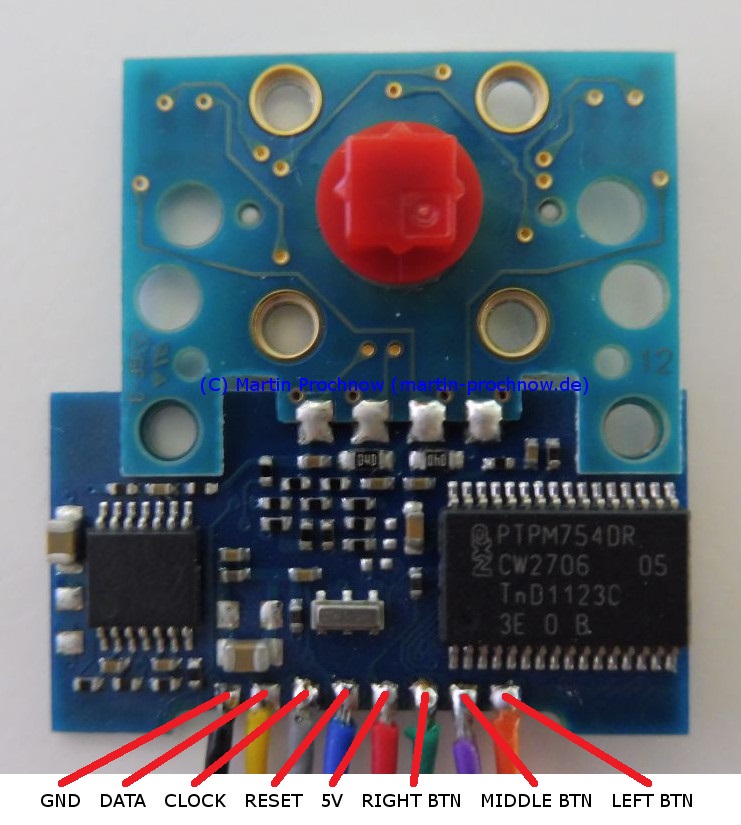
After much Googling, I found this: https://martin-prochnow.de/projects/thinkpad_keyboard which is the only other guy on the planet who seems to have accomplished what I am trying to accomplish with the ZD6 Trackpoint module. Props to him for blazing the trail and mapping the pinout.
Step by step:
1. Create the wiring to connect the Arduino and TrackPoint module
- Some guides say you need two 4.7K Ohm resistors. This is not true if you are using an Arduino.
- Heat-shrink is nice to have, but probably not necessary if you are connecting directly to the Keyboardio.
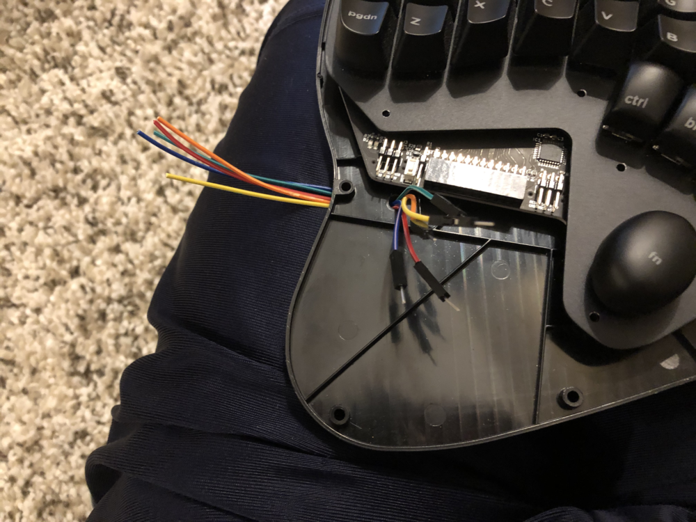
- I like to use red, orange, yellow, green and blue wires. Red is 5v, orange is reset yellow is clock, green is data, and blue is ground. This is the same order as the pins on the TrackPoint module I am using. Note that the below diagram does not have the Reset wire going to the Arduino. I’m not an expert in how “resets” work but I believe it depends on the software you are using to interface with the TrackPoint module. I have the reset going to the Arduino after it hits the capacitor as indicated by the diagram, and the software I am using expects it on the Arduino’s D4 pin.

2. Connect the TrackPoint to the Arduino.
Red - 5v - VCC pin on Arduino
Orange - reset - D4 on Arduino
Yellow - clock - D3 on Arduino
Green - data - D2 on Arduino
Blue - ground - GND on Arduino
3. Install software on Arduino
- Clone or Download the Github repo here. There are other repos you can use that will probably work. This one uses Stream Mode, which is the native operating mode of the TrackPoint module.
- Copy Trackpoint.h and TrackPoint.cpp to the TrackPoint_INT folder inside the repo.
- Open the TrackPoint_INT.ino file with the Arduino IDE
- Import Mouse.h by adding
#include <Mouse.h>underneath#include "TrackPoint.h"at the top of the file. - Ensure the Arduino Micro is the selected COM Port (Tools => Port), and Arduino Micro is the selected board (Tools => Board).
- Smash that Upload button to deploy the code to the Arduino.
It works pretty well, although tends to move the cursor on its own for the first few seconds after it is connected to a computer. I can move the cursor by touching the PCB around the red nub. I think this is just a testament to how sensitive it is. Touching the nub will wake the computer from sleep.
Adjust Sensitivity
Default sensitivity is much higher than my TrackPoint USB keyboard. To get them pretty close (so that I don’t have to change mouse sensitivity in OS when I go between the Keyboardio Trackpoint and other “mice”), I changed the argument on this method call in the TrackPoint_INT file: trackpoint.setSensitivityFactor(0x4b); // 0xC0 (192) is default
Resources:
An incomplete list of all the TrackPoint modules you might stumble into in the wild + pinout info
Wiring diagram (Arduino to TrackPoint)
The official TrackPoint spec (not needed for anything, but it’s neat)
The GitHub Repo for the Arduino software to power the TrackPoint
Stream Mode vs Remote Mode
Pinout for ZD6 TrackPoint module
Wiring diagram (where to put the resistor and capacitor)